
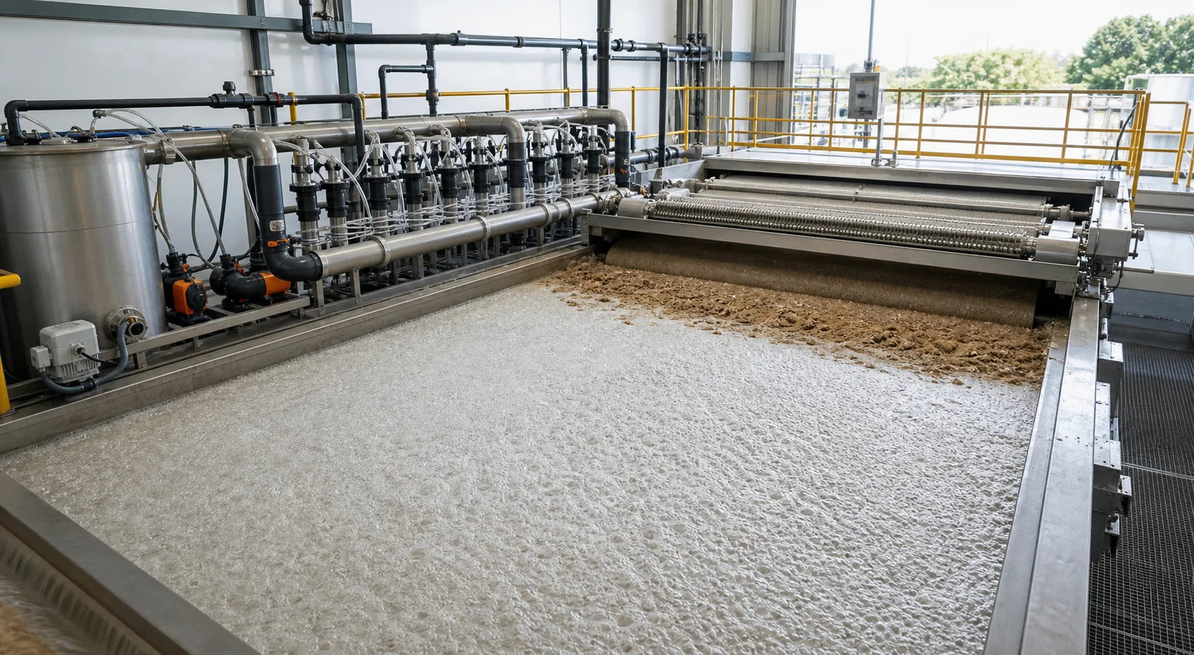
Define what the DAF must remove
DAF may target fats, oils, fibers, biological solids, metal precipitates or other suspended material. The solids composition determines coagulation demand and the floc structure needed for flotation.
Record flow, TSS, pH, oil and grease or other relevant indicators and current recycle conditions.
Stabilize pH and coagulation first
Primary coagulation changes particle charge and forms precipitates that PAM can bridge. A drifting coagulant window produces a drifting polymer result.
Set pH and primary dose before comparing PAM candidates, and preserve rapid-mix conditions.
Build flotation-ready floc
A good DAF aggregate must attach to microbubbles, rise and form a skimmable layer. Oversized dense floc can resist flotation, while weak floc breaks at recycle contact.
Observe bubble attachment, rise rate, float stability, clarified water and skimmer response rather than relying on settling alone.
Place the polymer where it can disperse
The injection point needs enough mixing to distribute diluted solution across the destabilized flow without destroying developed floc. Poor quill placement creates uneven dose.
Review pipe diameter, velocity, quill position, dilution flow and distance to the DAF inlet.
Protect floc at recycle contact
Pressurized recycle releases microbubbles and may impose hydraulic stress. The polymer program must tolerate that contact and preserve useful bubble-floc aggregates.
Include recycle ratio and saturator pressure in the operating record, even though polymer does not control those variables.
Use a complete dose curve
Underdose leaves pin floc and carryover. Overdose may cause stringy float, high viscosity, skimmer difficulty or downstream fouling.
Choose the lowest repeatable region meeting effluent and float-handling requirements.
Watch the sludge stream
Improved clarified water can still be offset by dilute float, poor drainage or higher sludge handling cost. Sample the float and its downstream dewatering response.
Include coagulant and PAM contributions when comparing total sludge production.
Verify the air and recycle side
A polymer screen cannot compensate for unstable recycle flow, inadequate saturation, blocked release devices or uneven bubble distribution. These conditions change attachment and rise independently of chemical selection.
Record recycle ratio, pressure and visible bubble condition during every comparison so the chemistry is not credited for an air-system change.
Inspect residual polymer effects downstream
Carryover can affect filters, biological units, membranes or sludge conditioning even when the DAF effluent initially looks clear. Observe the next unit and the recycle line during plant trials.
Use downstream pressure, fouling, solids or biological indicators as secondary stop limits when they are relevant to the treatment train.
Transfer with stop limits
Run one controlled product and dose step at a time, allow hydraulic residence time and define limits for pH, turbidity, carryover and float handling.
Retain the previous stable condition so operators can return safely if the trial response deteriorates. Record recycle pressure, loading, float solids and downstream response beside every chemistry change so later reviewers can reproduce the full DAF condition.